|
|
 |
|
Make your own vial-based protractor accurate up to 0.1°.
| Vernier Protractor |

|
| Click Picture To Enlarge |
|
|
|
If you have ever needed to accurately measure an angle with tools readily available at a hardware store, you would
have a difficult time getting accuracy better than one degree. Recently there have been new electronic devices including
the Beall Tilt Box, the Wixey angle finder, and a few others. You can even use an I-phone to measure vertical angles.
You could get more accurate by making test cuts and calculate an angle based upon measurements of lengths of sides of a triangle
using trigonometry - a rather slow and painful method. Older devices use a needle with a counterweight to indicate an
angle on a dial. The wide marks and needle are not more accurate than a degree if even that good, plus it only measures
the angle relative to true vertical and can not take into account if your table is a little bit out of level. I have
dreamed up a device that can be re-zeroed to compensate for a table that is not level or any vertical angle you want to call
relative zero - or you can set it to true horizontal using a level. It can be set to an angle and then locked down while
the angle is read in a more convenient position. The angle is read along a circular scale with one degree marks and
a vernier that allows the angle to be read to one tenth of a degree. I have made one for myself and using the information
on this page you can make one too. In the workshop I used the following tools to construct my protractor: bandsaw, tablesaw,
drill press, benchtop disc sander, spindle sander, pencil and compass. A router table could be substituted for the spindle
sander if needed, but the sander leaves a smoother finish and is much safer.
|
|
|
The degree circle and vernier must be drawn and printed very accurately in order for this device to obtain 0.1° accuracy.
I used an inkjet printer with Avery 18665 full-sheet see-through labels. This label is made of mylar instead of paper.
I know that some tape measures are made of mylar because it is strong and does not stretch or distort. The label sheets
already have adhesive and it sticks very well to smooth clean plywood. I feel that using mylar label sheets would not
degrade accuracy as much as paper and spray adhesive might.
|
|
|
The Vial - Another important
part of this device is the level vial. Level vials are made in a wide variety of sensitivity, most carpenters levels
use vials that have a sensitivity of around 38 minutes (0.63°) of arc per one tenth inch or 2.5 millimeters of movement
of the bubble. A bubble with this level of sensitivity will only move about .016" per 0.1° - not exactly a
lot of movement, that's roughly the width of the lines drawn on the vials. You can read a bubble more accurately
by using a magnifying glass and zeroing in with the end of the bubble just touching one of the lines rather than having it
centered between two of them. Empire level used to make a level with 9 minute vials - that's more than four
times more sensitive than levels made today. Currently they do not have any products that use the more sensitive vials.
If you can find a more sensitive vial you will get more accurate results. The more sensitive the better to a certain
point, there are such vials that would be too sensitive. You can draw a finer line on an acrylic vial by lightly cutting
it with a sharp blade and mark the scratch with ink and wiping off the excess ink around it. How it Works - Since this protractor uses a bubble level it can only
measure vertical angles. The bubble is zeroed up on a reference surface by rotating the disc that the vial is attached
to until the bubble is centered between marks and the front wing-nut is locked down. Then the protractor is placed on
a tilted surface and the larger disc is unlocked (using the wingnut on the back) and the disc is rotated until the bubble
is again aligned in the same position, then the rear wingnut is locked back down. The angle is read to a degree where
the long line on the left side of the vernier points to the degree scale - read the smaller number. The angle is then
read to a tenth of a degree by seeing which of the vernier lines matches up best end-to-end with the degree markings and added
to the degree measurement. The markings on the vernier are 0.9° apart. You might need a magnifier to see which
of the lines line up best with the degree markings. A larger circle of degree markings will be easier to read than a
small one, but we need the device to be small enough to fit on the side of a saw blade. It is possible to use this concept
to make a larger protractor with greater accuracy if you have an appropriate vial and the ability to print a larger degree
scale if you wanted to.
I finally settled on a vernier and degree scale with thin black lines. Mathematically, you could design a vernier
to break down the units into any fraction instead of just 1/10. I experimented with 1/12 (5 minute), 1/20 (3 minute),
and decided to go with 1/10 (6 minute). The 1/20° vernier was too hard to read, and I think most woodworkers would
prefer 1/10° over 1/12° to make the decimal to fraction conversion easier. For a protractor made of plywood,
I wouldn't feel comfortable trying to further improve the accuracy beyond 1/12°
| Face |

|
| Bubble and Outer Disc Removed |
Download the protractor scales as a PDF file. (4 inch scale)
Download the 6 inch version of the 0-360° protractor PDF.
Download Autocad 14 dwg of protractor template.
| Step 1 |

|
|
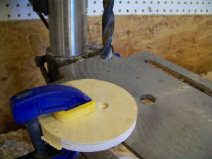
Apply the mylar label to a piece
of 1/2" plywood and draw a circle concentric to the scale that is large enough to include the corners of the protractor
inside. It is very important to center punch the center mark as accurately as possible to keep the drilled hole concentric
to the degree circle. Drill a 1/4" hole through the center and then roughly saw out the circle using a bandsaw,
jigsaw, or a scrollsaw. This larger circle will act as a guide later for precisely sanding the interior opening to size.
|
| Step 2 |

|
|
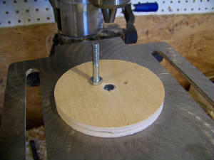
Make a circle-sanding jig out of a board with a 1/4" hole drilled through it. Use a snug fitting 1/4"
diameter bolt or rod as a pivot. It will help reduce chatter if the pivot is located so the board supports the disc to be
be sanded at the point where the sanding occurs. Clamp the jig securely in place on a benchtop disc sander with a c-clamp
and place the roughed-out disc onto the pivot. Rotate the wood disc into the spinning sander to make it perfectly round.
It will only need to be sanded enough that the sander touches the disc all the way around. Try not to sand off the square
corners of the protractor face. Use constant and even pressure against the pivot pin and make the final turn remove
a very small amount just barely touching the sanding disc.
|
| Step 3 |

|
|
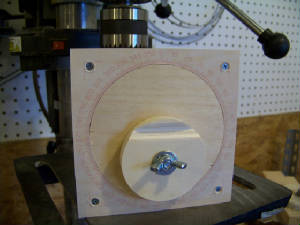
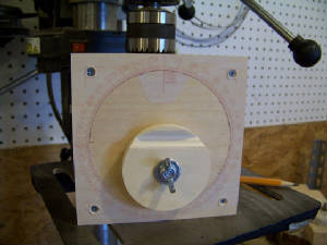
Drill a hole to thread the scrollsaw blade through and saw out the interior of the degree circle and stay about 1/16
to 1/8" away from the degree circle. Make a V-block jig for your spindle sander (or router table) as shown in the
picture and clamp it down so the outside of the ring is almost touching both sides of the V-block. This jig will sand
an interior circle that is concentric to the outer circle. If you centered your drill bit perfectly when you drilled
the 1/4" hole then the spindle sander should make a circle whose edge is concentric with the degree circle. Adjust
the V-block until you get the appropriate inside diameter which will be 4.000" (or 6.000") with the provided drawing.
Make sure you set up the spindle sander or router as shown. Do not position the V-block so the sanding sleeve or router
bit is on the portion of the circle down inside the V-block. If the disc were to move away from the V-block it should
also come out of contact with the sanding sleeve or router bit.
|
| Step 4 |

|
|
Make another plywood disc with a 1/4" hole in the center. Rough it out oversize with a bandsaw and then sand to
size on the disc sander jig. This will need to be just a hair smaller to fit inside the degree scale. You want
it to be a very close fit and still be able to rotate it easily either direction. Adjust the diameter made with the
sanding jig by gently tapping the board towards the sanding disc with another piece of wood or whatever is handy while the
sander is running. Check the diameter with a machinists caliper.
|
| Step 5 |

|
|
Using the cutout from step 3, rough out this shape leaving a flat side. This will be the disc holding the level
vial. Use the flat side against the fence on your router table to make the 90° V-groove to set the vial in.
The groove needs to be far enough away from the center hole so the wing-nut does not interfere. After the groove is
made, sand the part round to a diameter of about 2.5" Use a hot glue gun or epoxy to firmly attach the vial.
Press the vial into the glue so the vial is touching the sides of the V-groove.
|
|
| Step 6 |

|
|
Trim two adjacent sides of the body of the protractor. Consider using a bandsaw to make the first cut rather than
trying to cut a circle with a miter saw. Leave plenty of wood to trim off later with the tablesaw. After making
the second cut, trim off the bandsawn edge and then check the squareness between the two sides using a machinists square.
If the corner is out of square, this would be the best time to correct it. Later on you can use the protractor to check
the angle of each corner. Pre-drill and countersink the four screw holes for attaching the back.
|
| Step 7 |

|
|
Attach the back with wood screws. I used #4 3/4" screws. Leave the edges of the sides forming the corner
sticking out slightly so they will ride against the tablesaw fence. Trim the remaining two sides with the tablesaw and
then trim the first two sides so both pieces are cut at the same time. Now insert the disc and use it as a guide to
drill the center hole in the back. In this picture the fit was a little bit too loose so I tightened up the fit by shimming
with masking tape to keep the disc centered better while drilling the hole.
|
| Step 8 |
|
|
Use a 7/16" drill to make a shallow counter-bore for the bolt heads to be pressed into flush. Close the chuck on
your drill press and use another bolt as a ram to press the bolt head into the hole. This will prevent the bolt from
turning while adjusting the wing-nut. Flip the disc over and repeat for the bolt and disc that holds the level vial.
The side of the disc with the counter-bore in the center hole will be the side facing outward.
|
| Step 9 |
|
|
Press the bolt heads just below flush.
|
| Step 10 |
|
|
Assemble the three parts as shown. Use a washer and a wing-nut on both front and back sides of the protractor.
Almost finished!
|
| Step 11 |
|
|
Add the vernier to the inside disc. Line up the long line with a degree mark as close as you can and the mark on
the far right side of the vernier scale should line up perfectly with another degree line that is nine degrees ahead of the
first mark. You might need to trim a little bit off the ends of the marks on the scale if there is much difference between
the inside diameter of the degree circle and the outside diameter of the disc that fits inside the degree circle. The
vernier scale marks have an angle of 0.9° between them compared to 1.0° between the marks on the degree scale.
|
|
|
The completed vernier protractor. I added a pair of holes to the disc to make adjustment easier. Set the vial to
zero with another level to read angles relative to true horizontal. You could improve it more by cutting a notch in
the edge so it sits flat against the saw blade body and not the tooth tips. You could also inlay magnets.
|
|
|
A side view of the protractor shows both the front and back wing-nuts.
|
|
|
|
|
|
|
stevegarrison769@gmail.com
|
|
|
|