I originally got the idea to make wooden blinds as a useful project that would be a
practical use for my wooden gears I make with the technique I developed. Wood blinds are much nicer than cheap flimsy
plastic or metal blinds that are very common. Wooden blinds are also available commercially, but they are rather expensive
- especially when you have a room or house full of windows that need blinds. It seems to me like they wouldn't be
too difficult to make your own. The slats are easy to make and are just very thin bookmatched boards that could
be re-sawn on a bandsaw and sanded smooth. The top part needs three mechanisms: The raise/lower mechanism, the slat
angle adjustment, and a stop mechanism to securely hold the blinds in the desired position.
My design for blinds
places the part with the mechanisms above the window to prevent the handles from getting in the way of the slats, and also
to prevent blocking that much more window area. This creates a corner for all the lines to be directed around.
Some of the line guidance is pulleys, and some are eye screws. I found out real quick that eye screws alone create too
much friction for the raise/lower mechanism. It is possible to raise the blinds fully like this, but it takes quite
a bit of force. Pulleys are much more efficient in transmitting the force.
After I built two blinds
I learned that you can buy braided ladder for various width blinds by the foot through Levolor and other manufacturers.
I spent a lot of time building a rack to hold the slats in position as I painstakingly threaded and tied all the slats together.
Having this ladder material available eliminates the need for all that and will save a lot of time and frustration.
Much easier!
Walnut and Cherry Blinds
I should have used a wider board to make the slats from!
The top third is from a different board than the rest of the slats. The potential for book-matching the slats could
really make the blinds look that much nicer. A better color combination such as walnut and maple would look really good.
The raise/lower mechanism uses a system of pulleys and gears to wind up or let out two lines
that are attached to the bottom bar of the blinds. This line is threaded through holes drilled along the centerline
of each slat, goes through pulleys to be wound up onto a spool attached concentrically to the main gear. The gears are
not really necessary for the blinds to work properly, but they really add to the coolness factor! The pinion gear could
simply be replaced by a spool to wind the line up on. The two lines comes off the spool on the bottom and wraps
around a pair of larger pulleys - one on each of the two planes making the corner. This arrangement has the edges of
both pulleys slightly hanging over the corner by a distance that is the same as the the distance between the other
pulley groove and the board behind it. The exit tangent of the first pulley is the same as the entrance tangent on the
second pulley. From the second large pulley, the two lines split off and go to a pair of smaller pulleys that are vertical
over each suspension point on the bottom bar and thread through the center holes drilled in each slat.
The stop
mechanism is made up of a circle of holes drilled into the smaller pinion gear, and a peg protruding from the frame that lines
up with the holes. While the blinds are in any position other than at the bottom, there is a torque on the spool and
the main gear. The blind is designed so that the spool runs out of line exactly when the bottom bar reaches its lowest
position just above the window frame - the line could come off the pulleys if the weight of the lower bar did not keep tension
on the lines. The torque tries to turn the main gear counter-clockwise which pushes the pinion gear downwards and the
peg engages one of the holes preventing the gears and spool from turning.
Close-up of Gear Mechanism
The angle adjustment mechanism is simply a dowel with two pairs of strings wrapped a few turns around it in opposite directions.
As the dowel is turned, one pair of lines is taken up at the same rate that the other pair of lines is let out. Each
pair of lines is threaded through a small hole drilled through the dowel by folding the line in half and threading the ends
through the hole and then back through the loop making a Lark's head knot to prevent slipping. Wrap the two ends
around the dowel a few turns - this mechanism does not require much movement to change the angle of the slats. One pair
of lines goes through eye screws and joins the front strings of the slat ladders and the other pair goes to the other
side.
Angle Adjustment Control
The handles for the blinds need to be able to bend around
rather than vertical only. I made handles that join to the mechanisms through a universal joint made of wood and spring
pins. These are easy to make using a Forstner bit in a drill press. The part of the U-joint that is notched will
need to be cut out with a bandsaw. The ends need to be rounded over with a benchtop disc sander, and pivot holes need
to be checked for clearance before assembling the joint with a dowel, wood screw, or spring pin. Be sure to use
a kind of wood that is very strong such as hickory or pecan so the joint doesn't break apart during use. The raise/lower
mechanism takes a little torque to lift the slats and bottom bar which weigh over five pounds combined.
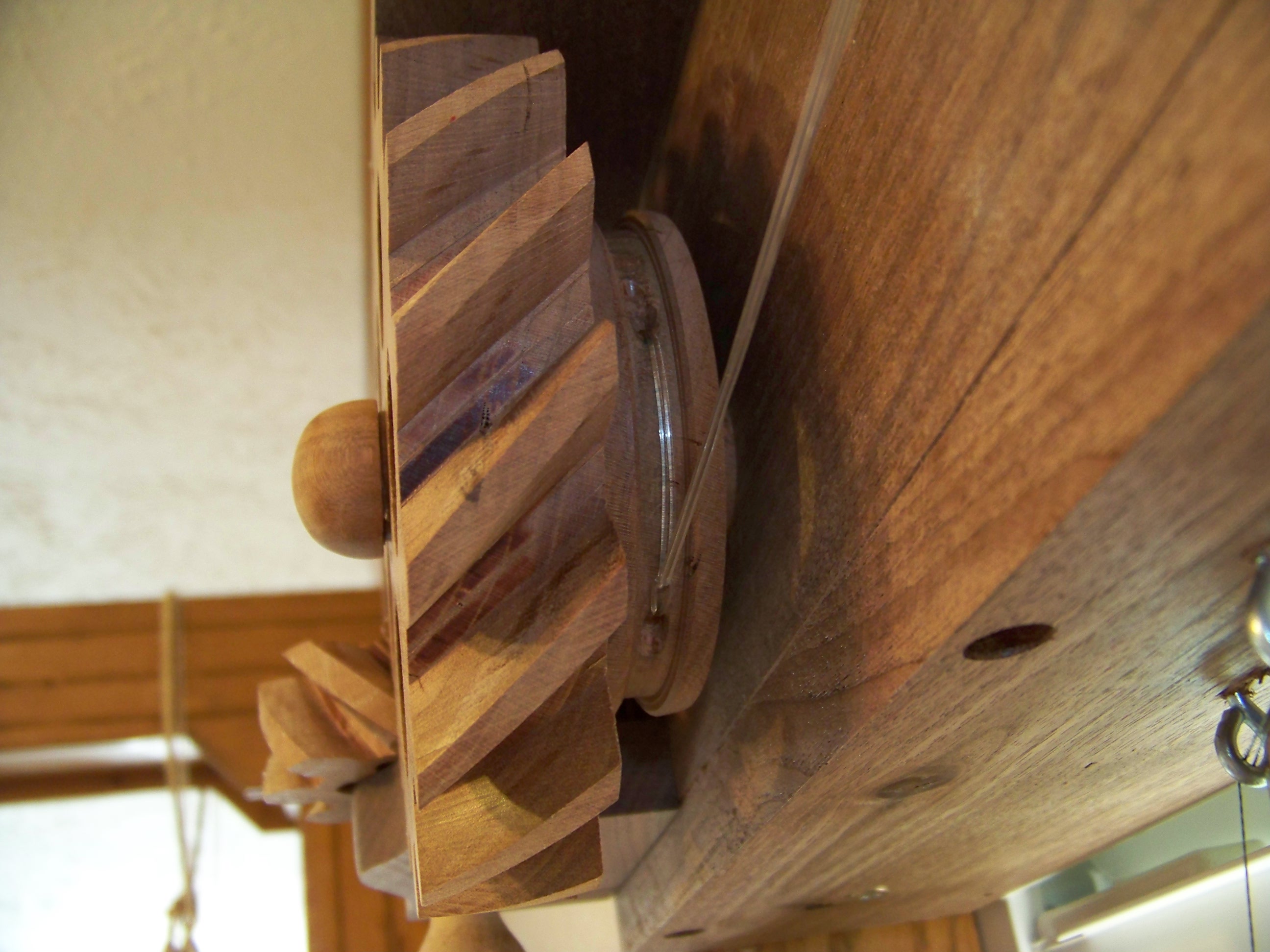
This is the lift line spool shown with the blinds lowered completely. A single line of 50 pound test monofilament is
doubled and the end pushed through the hole drilled through the groove in the spool. The other end is threaded through
the loop formed making a larks head knot.
From the main spool the two lines go over and around the two pulleys as shown. The exit tangent of the first pulley
is the same as the entrance tangent on the second pulley to keep the lines in the grooves. This enables the lines to
be directed around the corner. Rub a little beeswax on the bottom of the screw heads to keep the pulleys from squealing.
Use the screws to control friction on the pulley.
The two lift lines separate and go opposite directions from the second pulley.
The lift lines go over one last pulley which is located one quarter of the slat length from either end of the slats.
The line threads through 1/16" holes drilled along the centerline of the slats. At the bottom the line threads
through the bottom bar and is prevented from pulling out with an overhand knot. This knot must be placed at the location
where all the line on the spool is out so it holds the bottom bar just above the bottom of the window opening. If the
line were to go slack, it might come off the pulleys.
The angle adjustment lines are shown directed around the corner using pulleys. These pulleys could probably be replaced
with eyescrews. If so, you would want to have the eyes where the lines don't rub on the end of the wire forming
the eye. This situation would eventually either cut the lines, or the lines will pop out of the eyes.
Place the
eye screws so the line hits the pulleys square.
The angle adjustment is simply a dowel with two pairs of lines wrapped around it in opposite directions. Either way
you turn it, one pair will be taken up and the other pair let out. The lines in each pair are connected to the front
or back edge of the slats - one pair for the front, and the other pair to the back.