| Base Sphere 18 inch diameter |
|
| Click to enlarge |
|
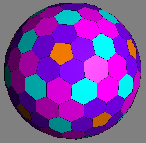
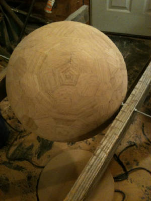
The base sphere is made of quarter-sawn red oak and has four
different face shapes - 12 regular pentagons and 150 irregular hexagons. There are also 6 different bevel angles which
are not a problem at all with my method I developed. The geodesic sphere makes very efficient use of material with little
waste. Geodesic spheres can have more or less sides than this one that I chose. More sides would have smaller
faces and be more round, but would be that much more work. The next step down would have been too soccer-ball looking
with 92 sides. I chose the dual instead of the geodesic sphere so the faces would be hexagons instead of triangles,
and the vertex points would be at the corners of 3 faces instead of 5 or 6.
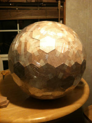
In this picture the faces have not
yet been rounded, and are just held together with masking tape and then stretch-wrap just to see how well the parts fit together.
In the next step the sphere will be taken apart so the faces can be rounded individually with my table saw jig. The
inside surface will not be exposed so I will leave the inside faces flat.
In hindsight I should not have bothered
with rounding the faces individually because it was very round already. I had to level the surface again anyway after
gluing to make it perfectly round.
|
| Glued |
|
| Click to enlarge |
|
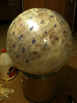
The last sphere I made only had 60 faces and I thought there
must be a better and faster way to glue them all together. With 162 faces (480 joints) it would have taken a long time
to glue it together a few edges at a time. I had an idea I decided to try, I put all the parts together as a sphere
with masking tape and then wrapped it with stretch wrap. Then I taped off an area around several faces to limit the
area that the wrap would pull back when I cut through it. I removed enough faces so that I could easily reach inside
and remove any masking tape that I had used on the inside. Now that the sphere is assembled and wrapped tight it didn't
need the tape on the inside. After getting all the tape out I marked one face as a drain plug and left tape around its
edges to keep the glue out. I poured about a half gallon of glue into the sphere and replaced the segment and wrapped
it up over the spot where I had opened it. Luckily the wrap was tight enough to prevent the glue from finding it's
way out. I rolled the ball around on the floor pushing down to flatten the bottom and open up the joints allowing glue
to flow into them. The tension in the stretch wrap would cause the segments to close back up into a sphere after the
pressure was released. It worked! I numbered each face and made sure that I had each one facing up to open up
the joints on the opposite side. When I was finished I taped around the drain plug and cut through the wrap to remove
it and then poured out the excess glue. Then I glued the drain plug back in place. What a time saver!
|
|
| Click to enlarge |
|
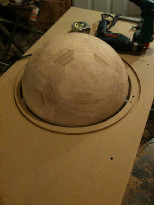
I chose the center of pentagons to represent the poles for my
globe. I drilled these two faces on my drill press with a 1/4" bit so the holes would be perpendicular to the surface.
I was a little nervous about threading a piece of 1/4" threaded rod through the sphere figuring the alignment was bound
to be off at least a little bit - I smiled when it found the opposite hole and pushed through without having to grind a point
on the end. A fixture is needed for measuring the surface and making it perfectly round. I drilled holes for the
axle in a pair of sawhorses and threaded the axle through and fastened it down tight to the sawhorse supports.
|
|
| Click to enlarge |
This fixture would also be useful for drawing latitude and longitude
lines on the globe if the marker or cutter were on the same plane as the axis of rotation.
|
I used a router with a large home-made circle cutting jig to make
a groove for the pencil mount and another circle that would be cut out with a jigsaw a little bigger than the diameter of
the sphere. Before I used the inner groove as a guide to cut out the hole I drew a straight line through the center
of the pivot hole. This line must align with the axle through the sphere to keep the globe spherical with equal radius
throughout. The sphere is also centered along the axis within the hole. Rotating the sphere in the fixture shows
the high and low areas where I had leveled off the edges that were not flush. The difference in radius between the highest
areas and the lowest looked like around 3/16 to 1/4 inch or so.
|
|
| Click to enlarge |
|
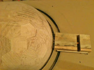
The pencil holder has two pegs in the bottom that ride
in the groove with a snug fit. The groove is lubricated with powdered graphite to make it easier to move. The
two pegs keep the pencil perpendicular to the sphere as it is moved around. The holder is made of two blocks of wood
and the block closer to the sphere has a groove cut on the bottom side for a sliding fit with a carpenters pencil. The
other block is fastened to the pencil by a tight friction fit. There is a screw driven into the end of one of the blocks
to act as a stop and limits the gap width between blocks - and the radius that the pencil point is at. The two
blocks have rubber bands on either side to keep either the rear block against the stop screw, or the pencil point against
the sphere when the pencil point is on a high spot.
The pencil draws a line on the sphere whenever the radius of
the high spot is more than the radius where the pencil point is. If the sphere has a smaller radius at the pencil point
then no line will be drawn. The sphere is rotated with the pencil holder in several places - perhaps 30° between
locations or so to mark the high spots. These areas are cut down with a flap disc sander on an angle grinder and then
gone over again with the pencil holder to see if the high spot has been cut down enough to clear the pencil point. After
the pencil no longer marks any high spots, the stop screw between the blocks is adjusted to reduce the radius where the pencil
point is and the process is repeated.
|
|
|
After the sphere is made concentric, latitude and longitude lines
were made with a router using a 1/16" veining bit at 15° intervals. I also decided to ebonize the wood using
a home-made solution of apple cider vinegar and steel wool. I tested a few different dyes and stains on scrap
pieces before choosing this method. Despite all the negative things I read about the vinegar-iron method with supposedly
variable results on oak, it turned out very nice. In the photo it appears to have some variation in darkness, but most
of that is caused by the grain direction not being parallel from one segment to the next. Later I learned about another
step in the ebonizing process that I did not use that adds tanin to the wood before the ebonizing solution is applied.
This would probably darken the color even more, but I am satisfied with it as is. The vinegar-iron method is also the
only method I tested that glue will adhere to.
|
|
|
The land masses are made from pieces of wood that have an internal
and external spherical curve of a radius to match the base sphere. I chose to break it down into individual countries
and states rather than just continents. The countries are made to fit together by overlapping inlays using a scroll
saw instead of intarsia. I want a tight fit without gaps between countries and this would have been difficult with intarsia.
In this photo is Africa right after I finished the inlays. I had to cut the continent into 3 pieces during the inlay
so the area I was working on would stay below the upper blade holder on the saw. Inlay work on a spherical workpiece
is not much different than a flat workpiece.
|
|
|
I chose South America to be the first continent to make while
I practiced my inlay skill. If I got off line a little bit then it would not be as likely to be noticed than it would
be if I goofed up a state. The overlapping inlay process starts with adding a different kind of wood to another piece
of wood. The only part of the cut that follows along a boundary is where the two countries join together and the rest
of the cut is made somewhere outside of the boundaries of both countries. Adding the next piece defines more of the
boundary where it touches the adjoining countries. This process is repeated for each country, and the countries touching
an ocean are also trimmed along the shoreline.
|